Medop Laboratory
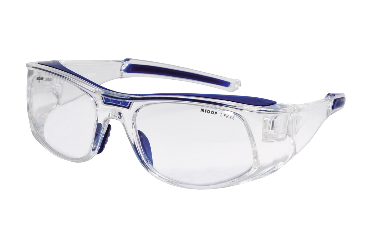
At Medop, we manufacture glasses, custom-fit earplugs, respiratory filters and aluminium lining. That is why we divide <Our Laboratory> into Eye, Hearing and Respiratory protection sections.
Manufacturing
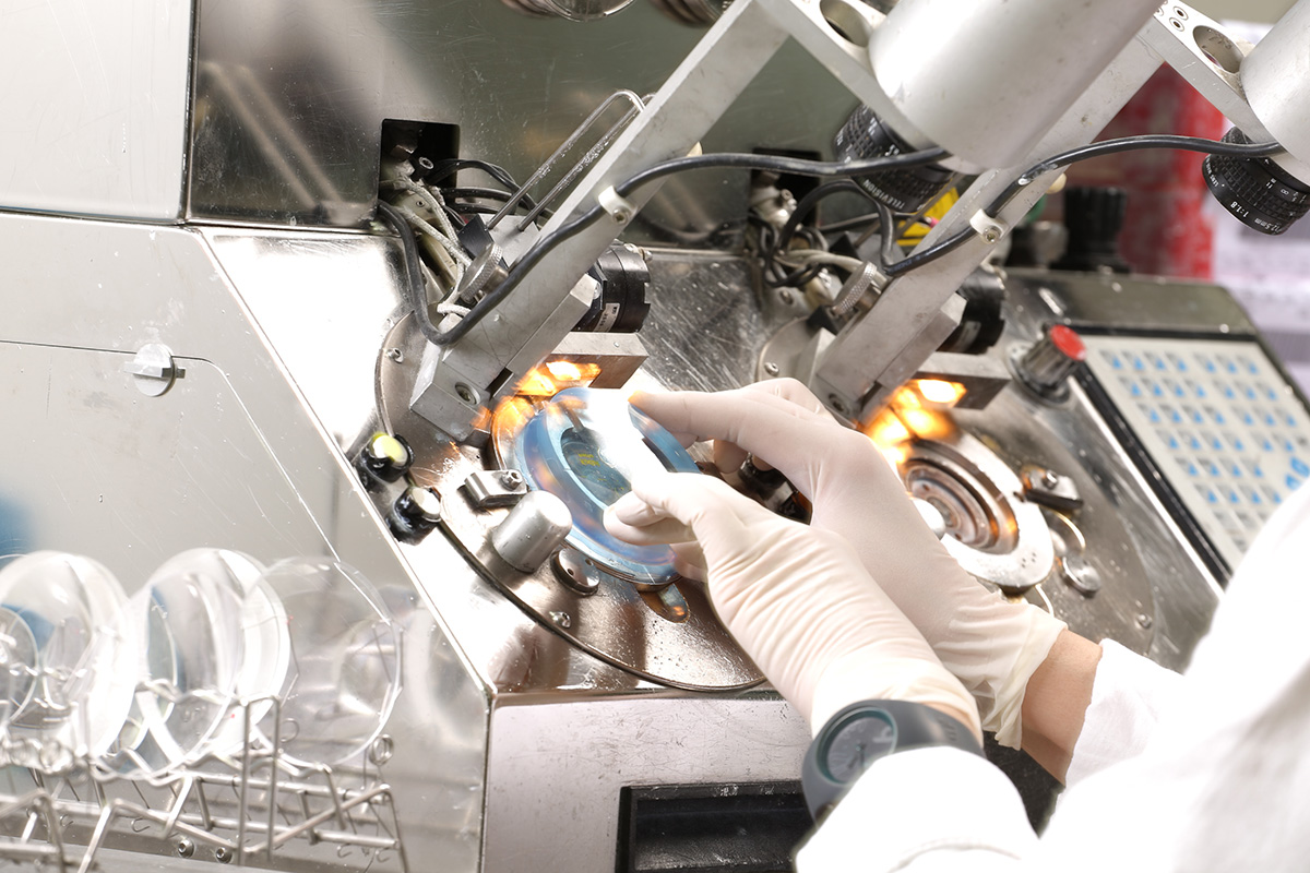
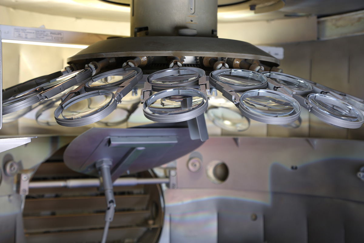
1. Preparing the lens: Shaping and polishing
A stock lens is selected, the lens is set in a metal vice and is then shaped; we have two cutting machines for this purpose. Once the lens has been shaped, the surface is polished. Finally, the lens is given an ultrasound cleaning.
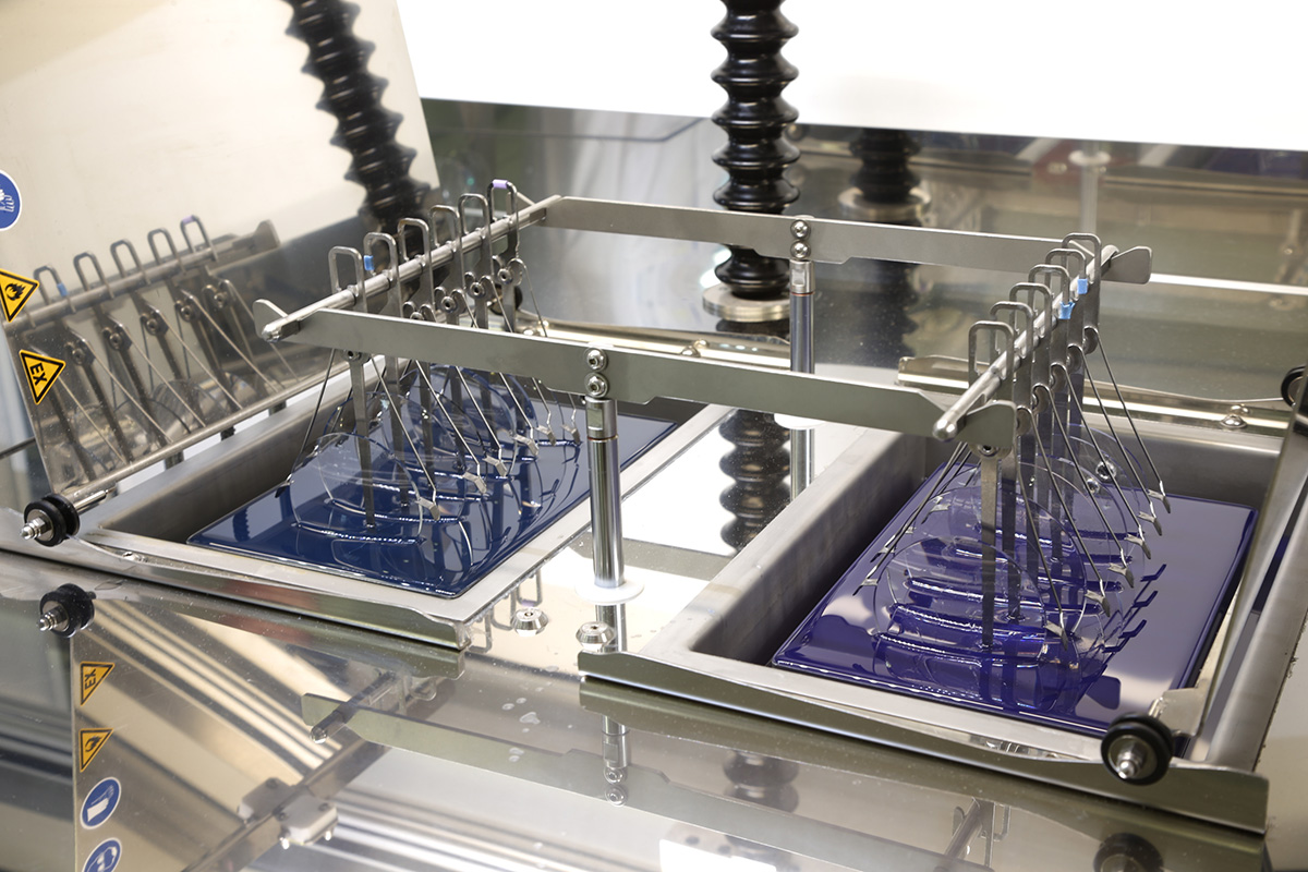
2. Colouring the lens
Colouring the lens is only done when the client requests it, for example, in sunglasses or optol lenses. To do this, we must first prepare the preparation, acceleration and recovery devices. Then, prepare the colour that will be applied to the lens.
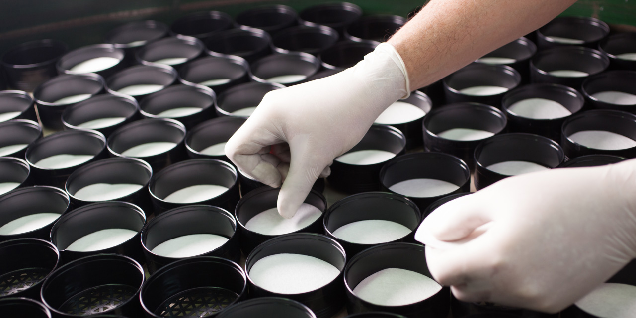
3. Treating the lens
Coating the lenses with anti-scratch varnish. First, the lens is given a prior cleaning. Then, the lenses are submersed in various buckets that contain soaps and varnishes where the hardener is applied. To finish, a baking procedure is performed.
4. Laser marking
Using a laser engraving machine, the corresponding CE marking is added to the lens.
5. Bevelling and assembly
Bevelling: the reporting system detects how the lens should be cut and a grinding wheel is used to create the shape for the frame.
Polishing: Once the lens has been bevelled, a polishing procedure is performed so that no ridges remain. Assembly: process where the lenses are joined to their corresponding frames.
Testing
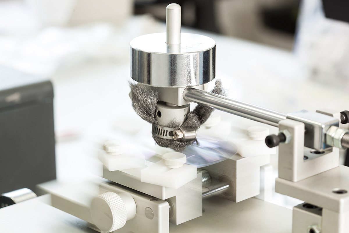
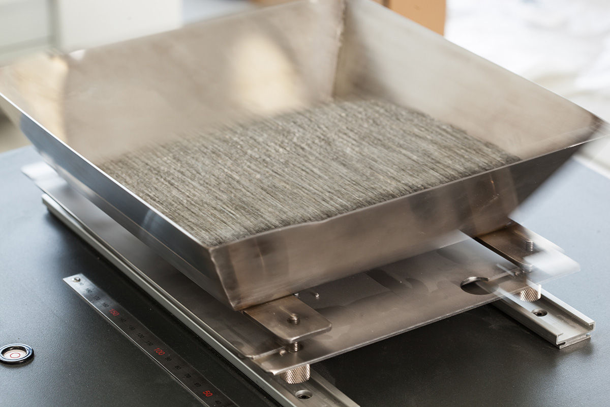
Steel wool
Used to test the hardness of the lens when scratched. On the lens to be tested, a line is drawn to indicate the area where the test will be performed. A piece of steel wool is placed on the machine arm, a 500 g weight is placed on it and then the machine rubs the lens 50 times. Then, the weight is changed to 1000 g and the lens is rubbed another 50 times.
Results: If the lens does not scratch at 500 g, it is acceptable, and if it exceeds this at 1000 g, it is good.
Crosshatch
Used to recreate factors potentially affecting coating adhesion. The lens to be tested is divided into 4 quadrants and multiple perpendicular cuts are made. Tape is stuck to each quadrant and quickly removed 3 times. The coating is checked for signs of lifting. If it does not lift, water is placed to boil and the lenses are submerged in it for 30 minutes.
Results: If the coating has not lifted, the result is good.
Bayer test
We move lenses around under a layer of sand to check their resistance to micro-impacts. We evaluate the results visually.

Boiling water test
Simulates lens wear, tests the robustness of the coating placed. Water is heated to 60 degrees Celsius and salt is added (60 g:1 L). Salt is dissolved into the water and the lens is submerged for 20 minutes. The lens is removed and dried, then the appearance is analysed.
Results: If the lens comes out without any wear, the result is good.
Bevelling test
Simulates the abrasion that a lens undergoes to its front/back sides during its useful life. The lens is set in the verifier. The lens is bevelled into any shape and cleaned, then held up to sunlight to see if the mark from the clamp can be seen.
Spectrometry
We can measure lens reflectiveness thanks to a spectrometer. We can measure lens reflection or transmission. We assume that the proper value should be above 97% of the total transmittance.
Manufacturing
1. Cast revision
Two initial casts are received that correspond to either ear of the user.
We must verify that the casts are correct. That is, that the concha and ear canal are perfectly defined, observing that the size of the ear aperture is sufficient and the ear canal is not missing any parts. The Otoblock is removed and the cast is cleaned.
2. Cast preparation
The ear canal is cut slightly after the second curve. The base should be as small as possible, leaving space for the filter. We round out all borders, drill in the centre about 6-10 mm deep with a diameter of 2.9 mm as perpendicular as possible. We repair any kind of imperfection in the mould with corrective wax.
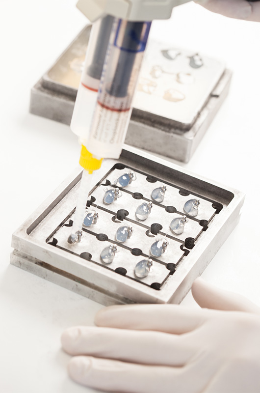
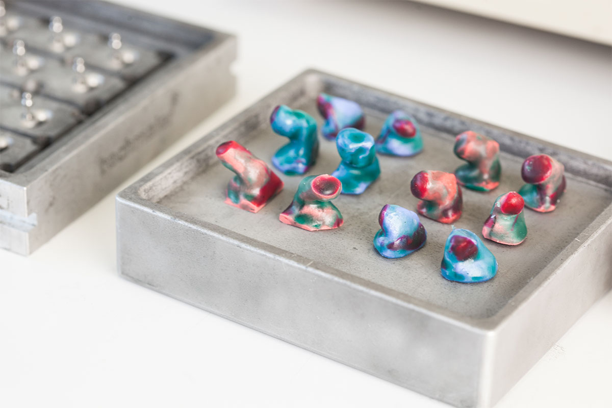
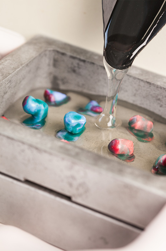
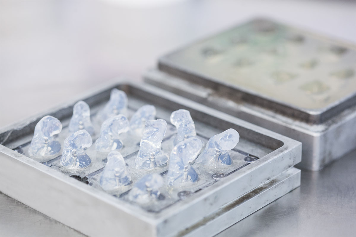
3. Injection
The casts are placed on the NEGATIVE MOULD tray. The mould is completely filled with a gel. It is placed into a machine at a set temperature for a specific time. Then, it is inserted into the refrigerator to solidify, then 30 min. into the freezer. The negative mould is filled. After this procedure, the earplugs are left to dry and are checked. If all is well, the plugs are then brought to be polished and varnished.
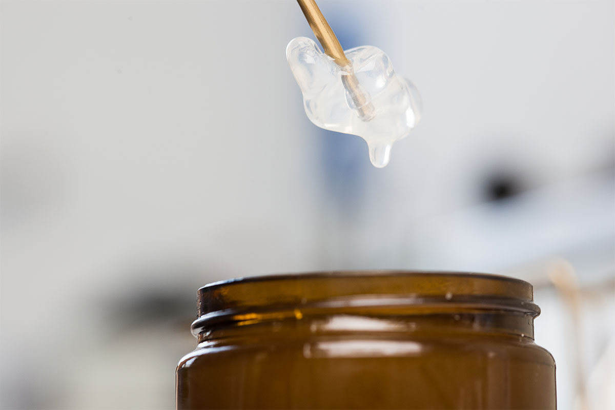
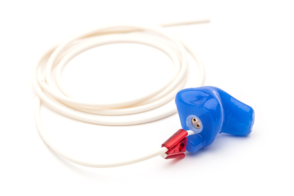
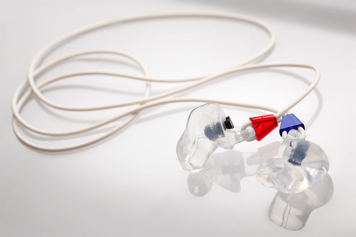
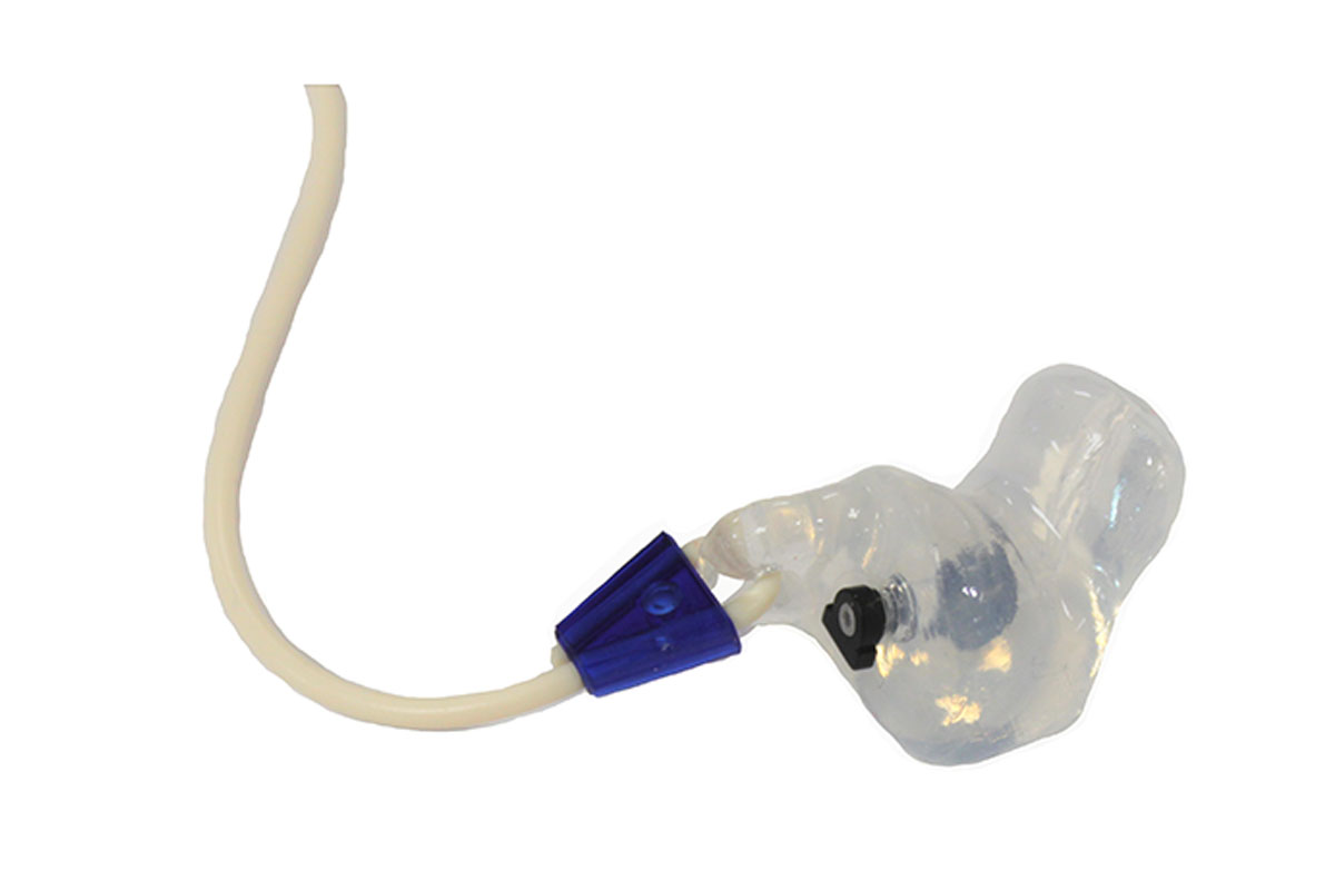
4. Assembly
A hole is made for threading the rubber cord, with red markings for the right earplug and blue for the left. The valve is placed and joined to the screw thread in the position requested. The hole made in the ear aperture is varnished, joining the valve to the hole so the final product is transparent and then is cleaned with propanol.
Testing
Verification of putty
The putty must be free of scales, pores, ridges, residues of a different colour and burrs from excess material.
Verification of the tab and cord
The tab is verified for appropriate size and to make sure it is the same in both earplugs in order to insert the cord and tighten the hooks.
Verification of symmetry
The apertures are verified to be the same and as symmetrical as possible, and the valve hole is verified to be well-placed.
Verification of valve
The varnish is checked and excess is removed from where the valve enters.
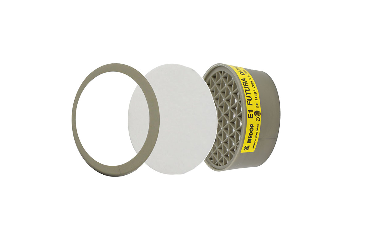
Manufacturing (Gas)
1. Revision of raw materials
Each time a new lot of carbon arrives, a pre-series of filters is made to test breathing resistance. Carbon lots are coded.
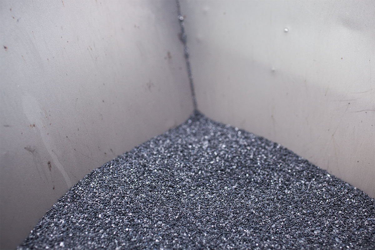
2. Filling the hopper
The hopper is filled with the amount of carbon needed for each type of filter to be produced. A carbon volume measuring tube is inserted to measure the volume needed for each type of filter.
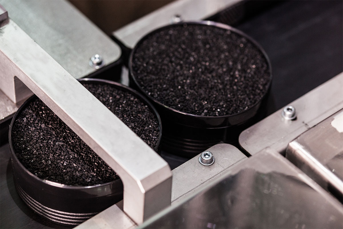
3. Manufacturing
The type of filter to be produced is selected: oval or round. Place carbon filling conveyor belt depending on the type of filer. Once the carbon filters have been filled, a pre-filter and the cap are placed on the filter.
4. Packaging and labelling
First, the label to be printed is selected and the placement position is determined based on the filter produced. Once the filters have been labelled, they are shrink-wrapped automatically.
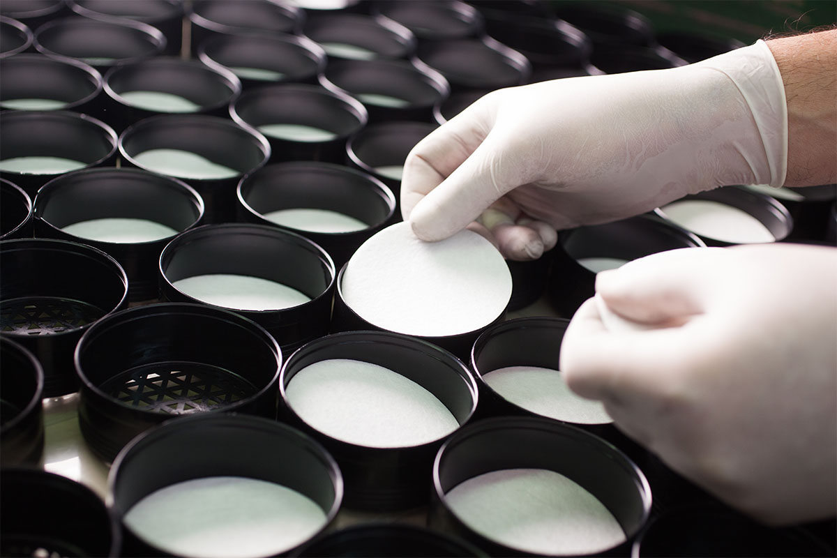
Manufacturing (Particles)
1. Roll placement
A particle filter is comprised of various layers of paper. The first thing that is done when producing these filters is to place the paper rolls in the order indicated by the layers that will constitute the filter. Once they are placed in the proper order, the layers are joined and laid on the press ram.
2. Die-casting
This is done using an automated system. The pressure used must be measured until all layers are separated. Once measured, the die-cast is placed over the layers of paper and they are die-casted. The final result is the layers of paper in a rectangular shape, some with a hole and others without.
3. Ultrasound welding and die-casting
The SonoTrodo is centred on the die-cast pieces with holes and central plastic piece that hooks into the central hole of the first layer of material is placed (so it remains in between both materials). We put the rest of the layers into place and then proceed to weld the layers. Now these are die-cast according to the type of filter: round or oval.
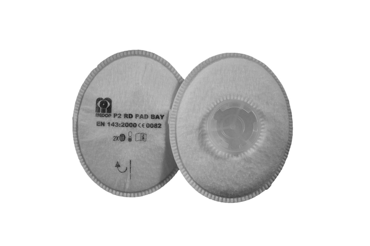
4. Screen-printing and packing
The filters are printed with the Medop logo, the filter markings and their regulations. Following this, the filters are packed and a sticker is placed indicating their reference number, lot and date of production.
Manufacturing (Combined)
1. Revision of raw materials and filling the hopper
Each time a new lot of carbon arrives, a pre-series of filters is made to test breathing resistance. The carbon lot is coded. The hopper is filled with carbon and the volume-measuring tube is inserted.
2. Manufacturing
The type of filter to be produced is selected: oval or round. The carbon filling conveyor belts are placed depending on the type of filer and the filters are filled up to the indicated weight and volume per filter.
3. Placement of roll, die-casting, and welding
The rolls for the different layers of paper comprising the filter are put into place, the layers are joined and are laid on the press ram. The filters are die-cast into a square shape and the layers are then welded onto the ring.
4. Packing
The two filters are pressed together using the packing machine.
5. Packaging and labelling
First, the label to be printed is selected and the placement position is determined based on the filter produced. Once the filters have been labelled, they are shrink-wrapped automatically.
Manufacturing (Nature)
1. Gas filter production process
First, the gas filter production procedure is followed: revision of raw materials, filling the hopper and production.
2. Inhalation membrane and pre-filters
Inhalation creases are made and die-cast. Once die-cast, each membrane is separated. Five layers of oval or round paper are selected and these are die-cast.
3. Cap + pre-filter
The pre-filter and cap are selected and sent through the welding process. In the case of combined filters, the filter will also go through packing.
4. Screen-printing and packing
The filters are printed with the Medop logo, the filter markings and their regulations. Following this, the filters are packed and a sticker is placed indicating their reference number, lot and date of production.
Testing
Carbon loss test
Once the production process has concluded and before shrink-wrapping, a carbon loss test is performed by hitting the filter. If it loses carbon, the filter is opened up and the carbon is reused.
Final test
Before packaging, filters go through a visual revision to detect aesthetic flaws, such as in the placement of the pre-filter, welding and cleaning; or labelling flaws, such as in sticker or label and shrink-wrapping, and it is checked for pores and to make sure it is well-sealed.
Breathing resistance
According to standard EN 14387, a chamber is used where the filter support is placed. The air is directed inside of the chamber and leaves through the filter and the attachment system. The test must be carried out with two different streams of air with the air at the ambient temperature, ambient atmospheric pressure and a humidity that does not produce condensation.
Mechanical resistance
According to the standard EN 14387, the apparatus consists of a steel box heavier than 10 kg, attached vertically to a vertically-moving piston. The filters are tested while sealed and are placed on either side of the box. It operates at a velocity of 100 rotations per minute over 20 minutes.
Gas resistance
According to the standard EN 14387, any method can be used to obtain an input airborne concentration of +/-10% of the indicated value and to measure the output concentration at +/-20% of the indicated value. The minimum saturation time must be measured using a flow of 30 l/min or at an appropriate flow level with a +/-3% tolerance.